
Overview
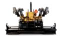
AS3251C screeds are rigidly built to handle the high demands of wide width paving. The heavy-duty frame prevents flexing and allows material to easily flow back to the extenders when increasing paving widths.


Specifications
| Weight - With Electric Heat | — |
| Standard Paving Width Range | 2.4-4.7 m (8-15.5 ft) |
| Maximum Paving Width | — |
Benefits & Features
Specifications
| Screed Type | Vibratory |
| Extender Mounting | Rear-mounted |
| Weight - With Electric Heat | — |
| Standard Paving Width Range | 2.4-4.7 m (8-15.5 ft) |
| Maximum Paving Width | — |
| Minimum Paving Width | — |
| Maximum Vibrator Frequency | 3000 vpm |
| Heating System | Electric |
| Crown Adjustment | +10% to –3% |
| Screed Plates Width, Front to Back, Main Screed | — |
| Screed Plates Width, Front to Back, Extenders | — |
| Length - Front to Back, Endgates Attached | — |
| Length - Front to Back, Endgates Removed | — |
| Minimum Width - Endgates Attached | — |
| Minimum Width - Endgates Removed | — |
| Height | — |
| Screed Plates Thickness | — |
Benefits & Features
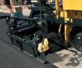
Rear-Mounted Extenders
Rear-Mounted Extenders
The extenders are mounted behind the main screed. This rearward location allows material to easily flow back to the extender when increasing paving widths.
Heavy-Duty Support Design
Two heavy-duty support tubes and a third frame member stabilize the extender and prevents flexing for even material flow.
Extender-Mounted Controls
The extenders include controls for adjusting paving width, material flow and tow-point height, convenient features when setting-up for wide width paving.
Integrated Harnesses
The electrical connections for the sonic feeder control sensors are integrated within the screed frame, eliminating the extra cord leading to the tractor.
Screed Plates
Screed Plates
The screed plates are constructed of an abrasion resistant alloy steel and utilize curved nose-bars to provide pre-compaction and good material flow.
Hydraulically Driven Vibrators
Hydraulically driven vibrators mounted on the main screed and extenders increase mix density under the screed.
Electric Heating Elements
The heating elements are located in each screed plate section to provide even heat distribution. The heating elements are reusable and can be easily removed and installed on new screed plates.
Uniform Heating
The heating elements provide uniform heat distribution over the entire screed plate for reliable operation.
End Gates
Spring-Loaded End Gates
The spring-loaded end gates create a downward force that cause the gates to follow the profile of the surface being paved, ensuring a good joint with the adjacent mat.
False-Wall Design
The false-wall design reduces mix contact with the sliding portion of the gate, providing easy gate adjustments.
Bolt-on Design
The bolt-on design allows easy end gate installation and removal when transportation concerns exist.
Foldable Handles
Foldable handles located on the end gate height adjustments allow them to be fully retracted when working close to barriers.
Dual-Bolt Guides
The dual-bolt guides allow smooth vertical movements and eliminate retention chains.
Control Panels
Conveniently Located Controls
The screed controls are conveniently located and easily recognizable to provide efficient operation.
Quick Angle of Attack Adjustment
The thickness control screws utilize spinner handles for easy angle of attack adjustments.
Electric Heat Control Panel
The electric heat control panel includes three temperature settings that are able to accommodate a variety of asphalt mixes and paving conditions.
Electric Heat Controller
An electric heat controller automatically regulates screed plate temperatures to the selected setting. The controller also assists troubleshooting procedures with minimal training.
Serviceability
Quick Screed Plate Adjustment
The threaded-bolt design located on the front and rear edge of the screed plates eliminate shims to provide quick replacement and leveling.
CANbus Electrical System
The CANbus electrical system utilizes a controller to perform screed functions, eliminating many wires and relays for a reliable electrical system.
CANbus Interface
The CANbus electrical system on the screed provides an interface with the Advisor display on the tractor for simplified diagnostics. The system is compatible with Cat ET.
Color-Coded Electrical Wiring
Cat® electrical harnesses utilize a kevlar braid and nylon mounting blocks to protect against abrasion. The wires are color-coded and numbered for fast reference.
Data not available.