836
836 - 2022, Tier 4 Final, EU Stage V, Korea Stage V and Japan 2014 - GlobalOverview
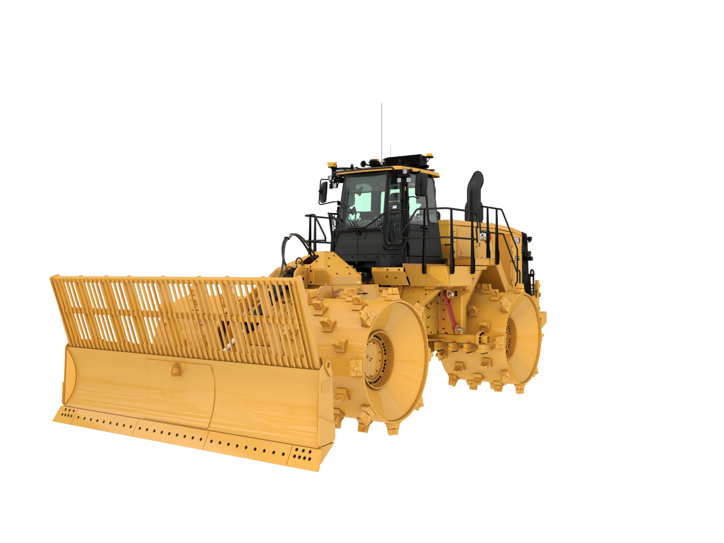
Cat Landfill Compactors are designed with durability built in, ensuring maximum availability through multiple life cycles. With optimized performance and simplified serviceability, our machines allow you to operate more efficiently and safely. Introduced in 1993, the 836 has been an industry leader for over 30 years. Focused on helping our customers succeed, we have continued to build upon each new series. The 836 continues our legacy of reliability, performance, safety, operator comfort, serviceability, and efficiency.
Specifications
Units:
| Gross Power - SAE J1995:2014 | — |
| Net Power - SAE J1349:2011 | — |
| Net Power - ISO 9249:2007 | — |
Benefits & Features
June 20, 2025
Specifications
Units:
| Gross Power - SAE J1995:2014 | — |
| Net Power - SAE J1349:2011 | — |
| Net Power - ISO 9249:2007 | — |
| Engine Power - ISO 14396:2002 | — |
| Emissions | U.S. EPA Tier 4 Final, EU Stage V, Korea Stage V and Japan 2014 or Brazil MAR-1, equivalent to China Nonroad Stage III/U.S. EPA Tier 3/ EU Stage IIIA |
| Engine Model | C18 |
| Rated Speed | 1900 rpm |
| Peak Torque ( 1,400 rpm ) | — |
| Torque Rise | 52% |
| Bore | — |
| Stroke | — |
| Displacement | — |
| High Idle Speed | — |
| Low Idle Speed | — |
| Maximum Altitude - Without Derating | — |
| Note | Net power advertised is the power available at the engine flywheel when the engine is equipped with a fan, air cleaner, clean emissions module and alternator. |
| Operating Weight (Tier 4 Final/Stage V) | — |
| Operating Weight (Tier 3/Stage IIIA equivalent) | — |
| Maximum Operating Weight (Tier 4 Final/Stage V) | — |
| Maximum Operating Weight (Tier 3/Stage IIIA equivalent) | — |
| Transmission Type | Planetary - Powershift - ECPC |
| Direct Drive - Forward 1 | — |
| Direct Drive - Forward 2 | — |
| Direct Drive - Reverse 1 | — |
| Direct Drive - Reverse 2 | — |
| Lift System - Circuit | Flow Sharing Implement; Pilot Operated LS Valve w/EH |
| Lift System - Pump | Variable displacement piston |
| Max Flow @ 2000 rpm | — |
| Relief Valve Setting - Lift | — |
| Cylinders, Double Acting: Lift, Bore, Stroke | 137.9 mm x 1021 mm (5.5 in x 40.2 in) |
| Pilot System | Variable displacement piston |
| Pilot Relief Valve Setting | — |
| Steering System - Circuit | Flow Sharing Implement; Pilot, load sensing |
| Steering System - Pump | Piston – Variable Displacement |
| Max Flow @ 2000 rpm | — |
| Relief Valve Setting - Steering | — |
| Total Steering Angle | 86 |
| Steering Cycle Times - High Idle | — |
| Steering Cycle Times - Low Idle | — |
| Fuel Tank | — |
| Diesel Exhaust Fluid Tank | — |
| Cooling Systems - Tier 4 Final/EU Stage V | — |
| Cooling System - Tier 3/Stage IIIA Equivalent | — |
| Engine Crankcase | — |
| Transmission | — |
| Differential - Final Drives - Front | — |
| Differential - Final Drives - Rear | — |
| Hydraulic System - Implement/Steering | — |
| Hydraulic Tank Only | — |
| Note | - All nonroad Tier 4 Final/Stage V diesel engines are required to use: - Ultra low sulfur diesel (ULSD) fuels containing 15 ppm (mg/kg) for EPA and 10 ppm (mg/kg) for EU sulfur or less. Biodiesel blends up to B20 are acceptable when blended with 15 ppm (mg/kg) sulfur or less ULSD and when the biodiesel feedstock meets ASTM D7467 specificiations. - Cat DEO-ULS™ or oils that meet the Cat ECF-3, API CJ-4, and ACEA E9 specifications are required. - Diesel exhaust fluid (DEF) that meets all requirements defined in ISO 22241-1:2006. |
| Air Conditioning | • The air conditioning system on this machine contains the fluorinated greenhouse gas refrigerant R134a or R1234yf. See the label or instruction manual for identification of the gas. • If equipped with R134a (Global Warming Potential = 1430), the system contains 1.4 kg (3.1 lb) of refrigerant which has a CO2 equivalent of 2.002 metric tonnes (2.206 tons). |
| Front | Planetary – Fixed |
| Rear | Planetary – Oscillating |
| Oscillation Angle | ±6° |
| Service Brakes | Multi Disc Wet (Enclosed) 2 WHL |
| Parking Brake | Spring Applied, Hydraulic Released |
| Operator Sound Level (ISO 6396:2008) - Standard | — |
| Machine Sound Level (ISO 6395:2008) - Standard | — |
| Operator Sound Level (ISO 6396:2008) - Suppression | — |
| Machine Sound Level (ISO 6395:2008) - Suppression | — |
| Note (1) | The operator sound pressure level was measured according to the test procedures and conditions specified in ISO 6396:2008. The measurements are conducted at 70% of the maximum engine cooling fan speed. |
| Note (2) | Hearing protection may be needed when the machine is operated with a cab that is not properly maintained or when the doors or windows are open for extended periods or in a noisy environment. |
| Note (3) | The machine sound power level was measured according to the test procedures and conditions specified in ISO 6395:2008. The measurements are conducted at 70% of the maximum engine cooling fan speed. |
| Height to Top of Beacon | — |
| Height to Top of Air Conditioning Condenser | — |
| Height - Cab Roof | — |
| Height - Top of Exhaust Pipe | — |
| Height - Top of Hood | — |
| Ground Clearance to Hitch | — |
| Ground Clearance to Transmission Guard | — |
| Ground Clearance to Bottom of Bumper | — |
| Centerline of Rear Axle to Rear Compactor Guard | — |
| Hitch to Centerline of Front Axle | — |
| Wheel Base | — |
| Width over Front Striker Bars | — |
| Width over Rear Striker Bars | — |
| Width over Platform | — |
| Width over Drums | — |
| Overall Machine Length with Semi U-Blade | — |
| Capacity | — |
| Overall Width | — |
| Height | — |
| Height of Cutting Edge | — |
| Digging Depth | — |
| Ground Clearance | — |
| Turning Radius – Outside Corner of Blade | — |
| Turning Radius - Inside of Wheels | — |
| Weight | — |
| Total Operating Weight | — |
| Capacity | — |
| Overall Width | — |
| Height | — |
| Height of Cutting Edge | — |
| Digging Depth | — |
| Ground Clearance | — |
| Turning Radius – Outside Corner of Blade | — |
| Turning Radius – Inside of Wheels | — |
| Weight | — |
| Total Operating Weight | — |
| Capacity | — |
| Overall Width | — |
| Height | — |
| Height of Cutting Edge | — |
| Digging Depth | — |
| Ground Clearance | — |
| Turning Radius – Outside Corner of Blade | — |
| Turning Radius – Inside of Wheels | — |
| Weight | — |
| Total Operating Weight | — |
| Combination Tips (Weight Group) | — |
| Plus Tips - Weight (Group) | — |
| Paddle Tips - Weight (Group) | — |
| Chopper Tips (Weight Group) | — |
| Diamond Tips Weight (Group) | — |
| Outside Diameter | — |
| Outside Diameter - Diamond | — |
| Drum Diameter | — |
| Drum Width | — |
| Feet Per Row | 8 |
| Feet Per Wheel | 40 |
| Replaceable | Weld on |
| Width Over Drums | — |
| Tip Height | — |
| Tip Height - Diamond | — |
Benefits & Features
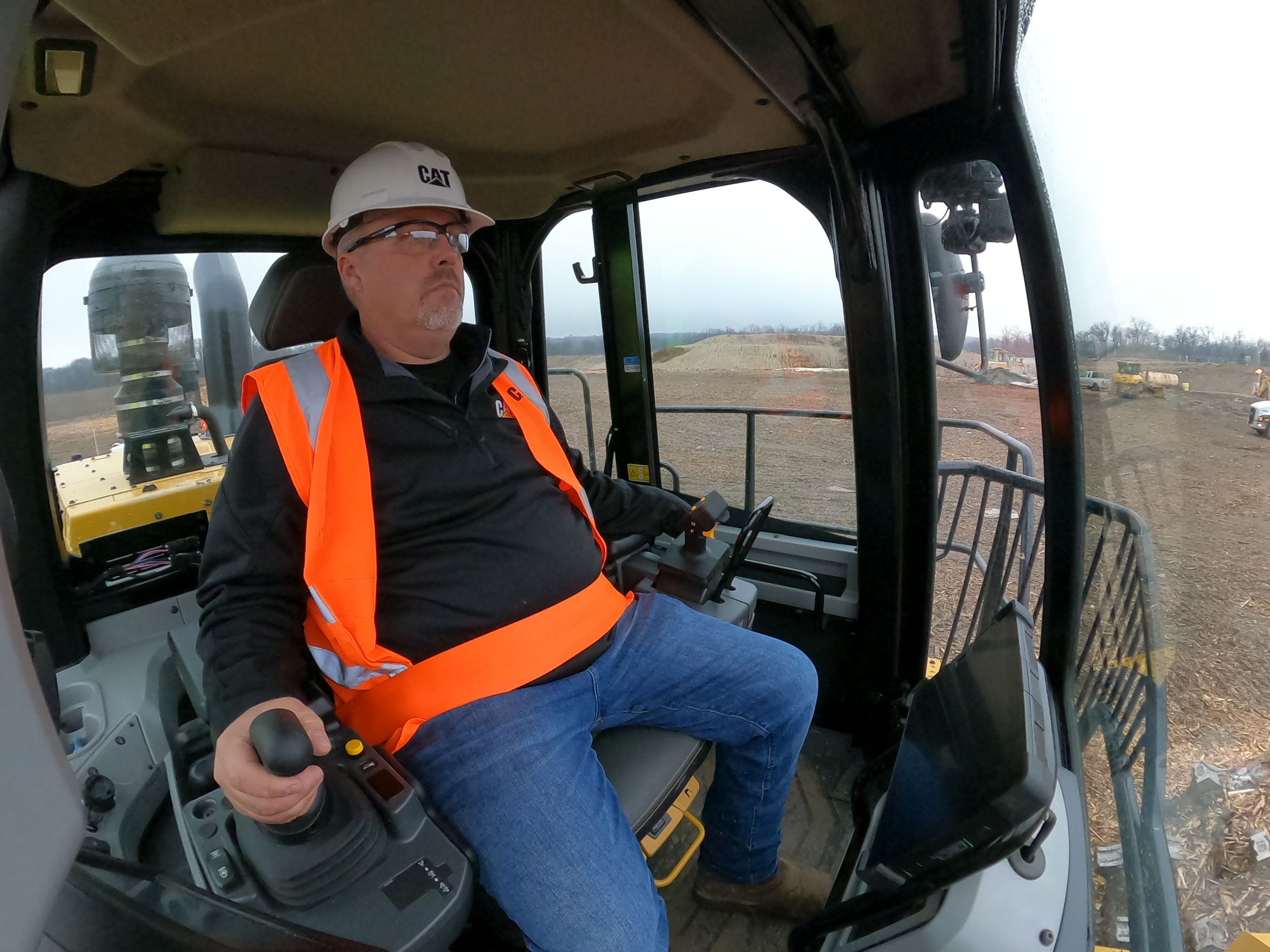
OPERATOR COMFORT AND CONTROL
- Flip-up armrest for easy ingress/egress.
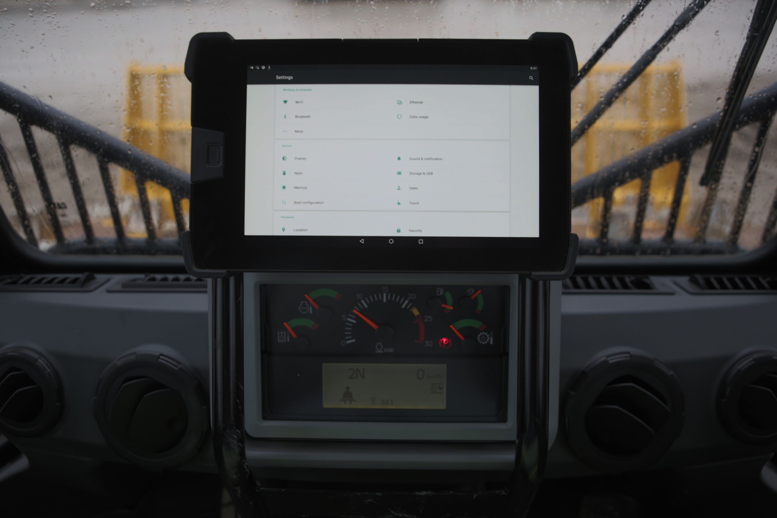
- Keep your operators informed about machine conditions and operation with Vital Information Management System (VIMS™) 3G machine monitoring system.
- Enhanced visibility with standard rearview camera.
- Preferred temperature settings maintained with automatic climate control.
- Cat Premium Plus seat with standard features including leather finish, forced air heating and cooling, two-way thigh adjustment, power lumbar and back bolster adjustment, and dynamic end dampening to help provide total comfort throughout the workday.
- Increased forward visibility with lowered glass for better visibility to the blade and wheels.
BECAUSE UPTIME COUNTS
- Easy access and in a controlled environment; electronics bay is located inside the cab.
- Focused on safety with ground level or platform access to most major components.
- Ground level: emergency shutdown, battery disconnect, and jump start.
- Quick visual inspection and minimize fluid contamination with sight gauges for coolant, transmission, and hydraulic oil.
- Electronic air inlet restriction indicator.
- Designed for ease of service and inspection– Hydraulic oil cooler, fuel cooler, and roof-mounted condenser– Centralized grease points.
- Operators and technicians can resolve any problems before failure using VIMS.
- Underhood lighting for improved visibility of service points.
- Improved guarding around the axles mitigates risk of damaged components.
- Improved radiator air inlet door sealing to help reduce radiator cleanout.
- Remaining useful life of the engine air filter helps allow for better planning of maintenance and repair activities.
POWERFUL EFFICIENCY
- Improved performance, long life, low emissions.
- High productivity and fuel efficient.
- Two engine options available that meet U.S. EPA Tier 4 Final, EU Stage V, Korea Stage V, and Japan 2014 emission standards or Brazil MAR-1 and China Nonroad Stage III emission standards, U.S. EPA Tier 3 and EU Stage IIIA equivalent.
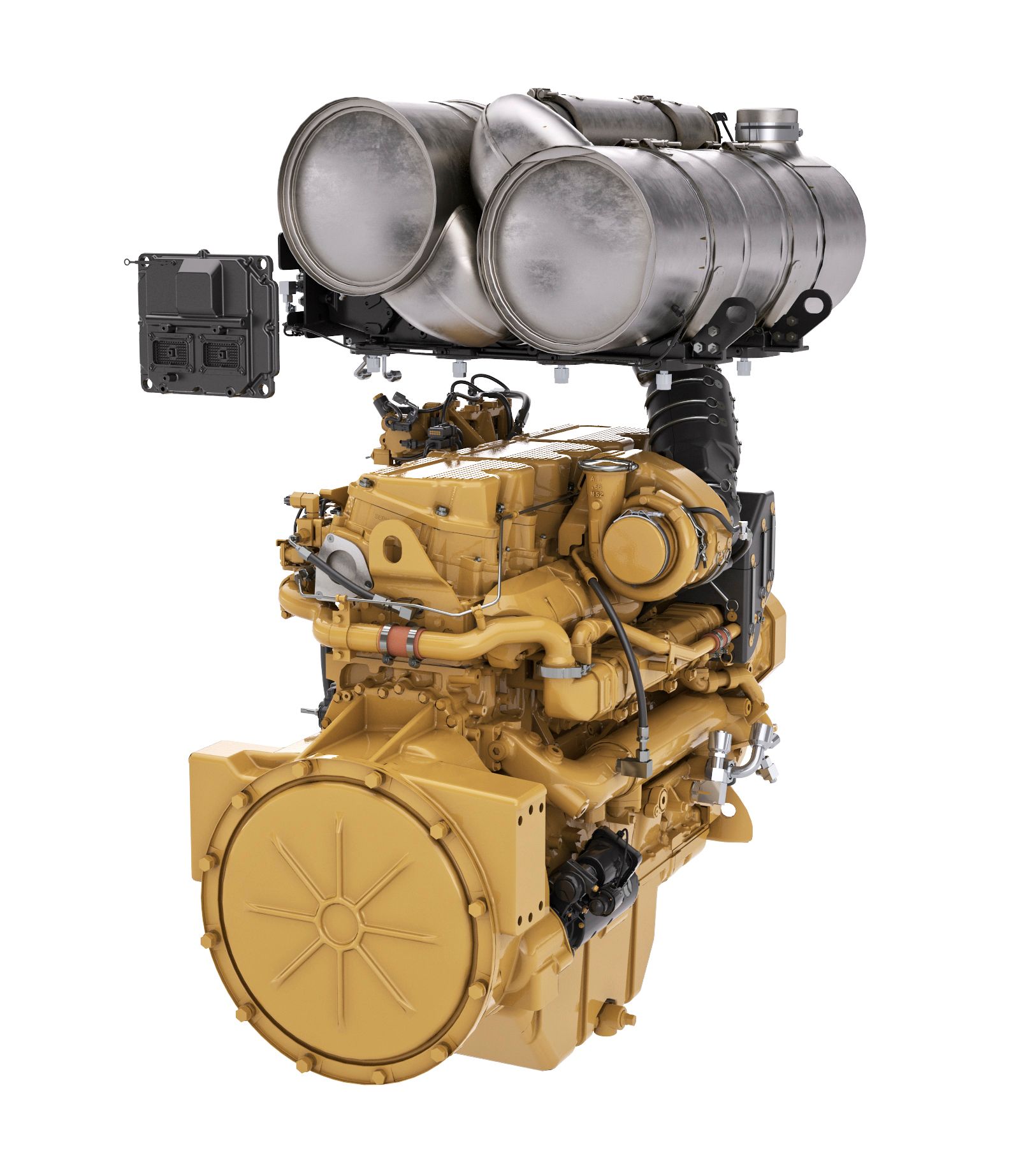
- For the Tier 4 Final, EU Stage V, Korea Stage V, and Japan 2014 option, the Cat Clean Emissions Module contains a diesel oxidation catalyst, diesel particulate filter, and Cat Regeneration System, utilizing selective catalytic reduction (SCR) technology.
- Regeneration is completely automatic and does not interrupt the machine’s work cycle.
- Experience maximum responsiveness and control with Steering and Transmission Integrated Control System (STIC™).
- Conserve more fuel with the automatic engine and electrical system shutdown.
- Achieve greater momentum on grades and fuel savings by carrying that momentum through the shift points advanced productivity electronic control system (APECS) transmission controls.
- Operators experience less fatigue with throttle lock to maintain engine speed.
- Equipped with Cat torque converter with lock-up clutch which eliminates torque converter (TC) losses while lowering system heat and transfers more power to the ground.
- Improved direction shift speed with new Cat locker differentials.
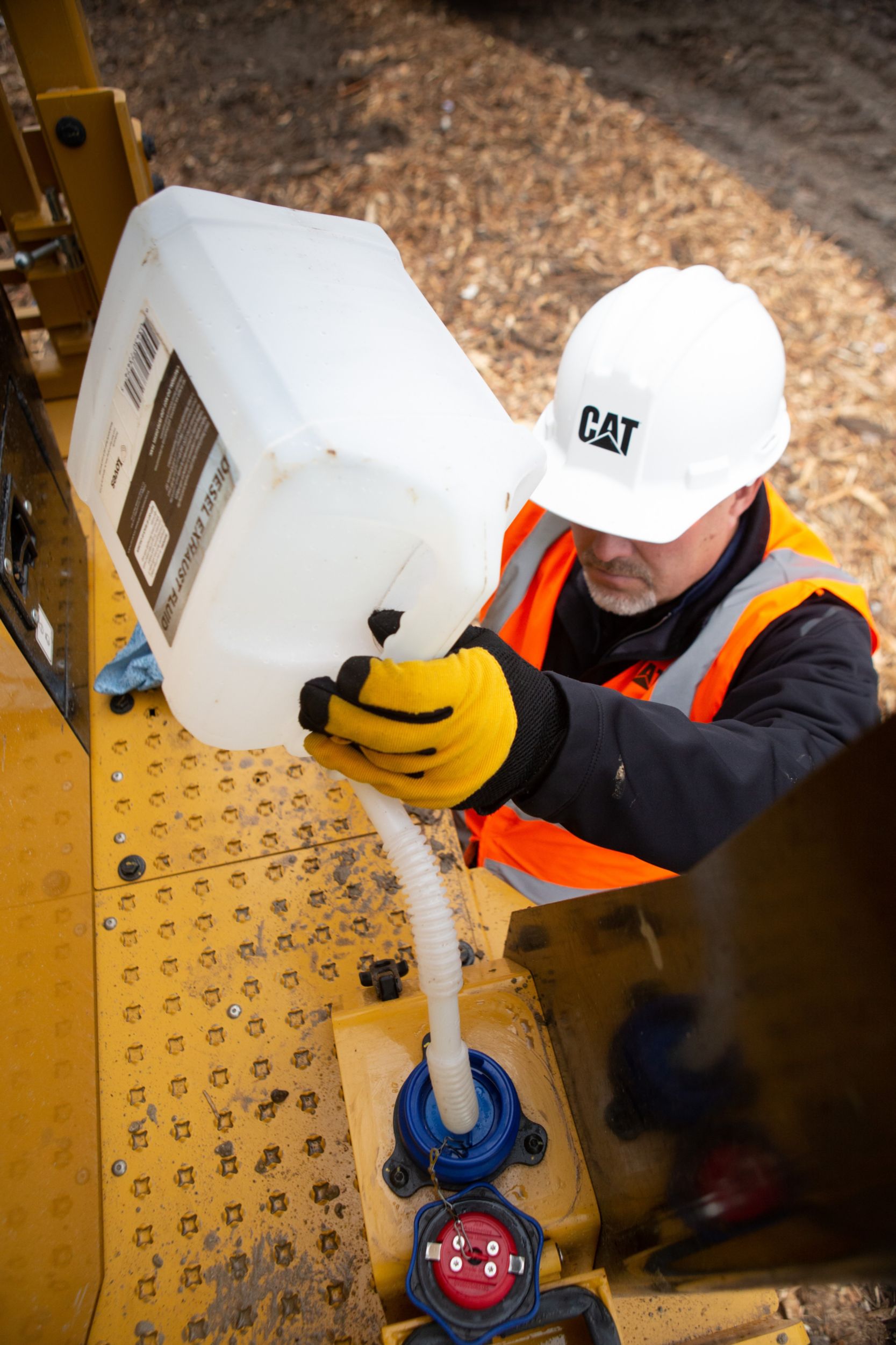
- Diesel exhaust fluid (DEF) injector phase change tank to reduce engine idle time at shutdown.
- Increase machine tarp lift capability to eliminate need for track type tractor to carry tarp rolling equipment for end of day landfill cover.
PRODUCTIVITY WITH TECHNOLOGY
- Compact technology combines advanced compaction measurement, in-cab guidance, and reporting capabilities to help you consistently meet compaction targets fast, uniformly, and in fewer passes – saving on fuel and the cost of unnecessary rework.
- Link technology (standard) provides access to machine location, hours, fuel consumption, idle time, events, and diagnostic codes through the online VisionLink® interface.
- Improved productivity with standard Cat Compact with Pass Mapping and 10" display.
- Slope indicate feature helps improve construction of slopes and identifies when risk for fluid cavitation occurs.
- Improved productivity with optional Cat Compact with Elevation Mapping.
LONG TERM VALUE AND DURABILITY
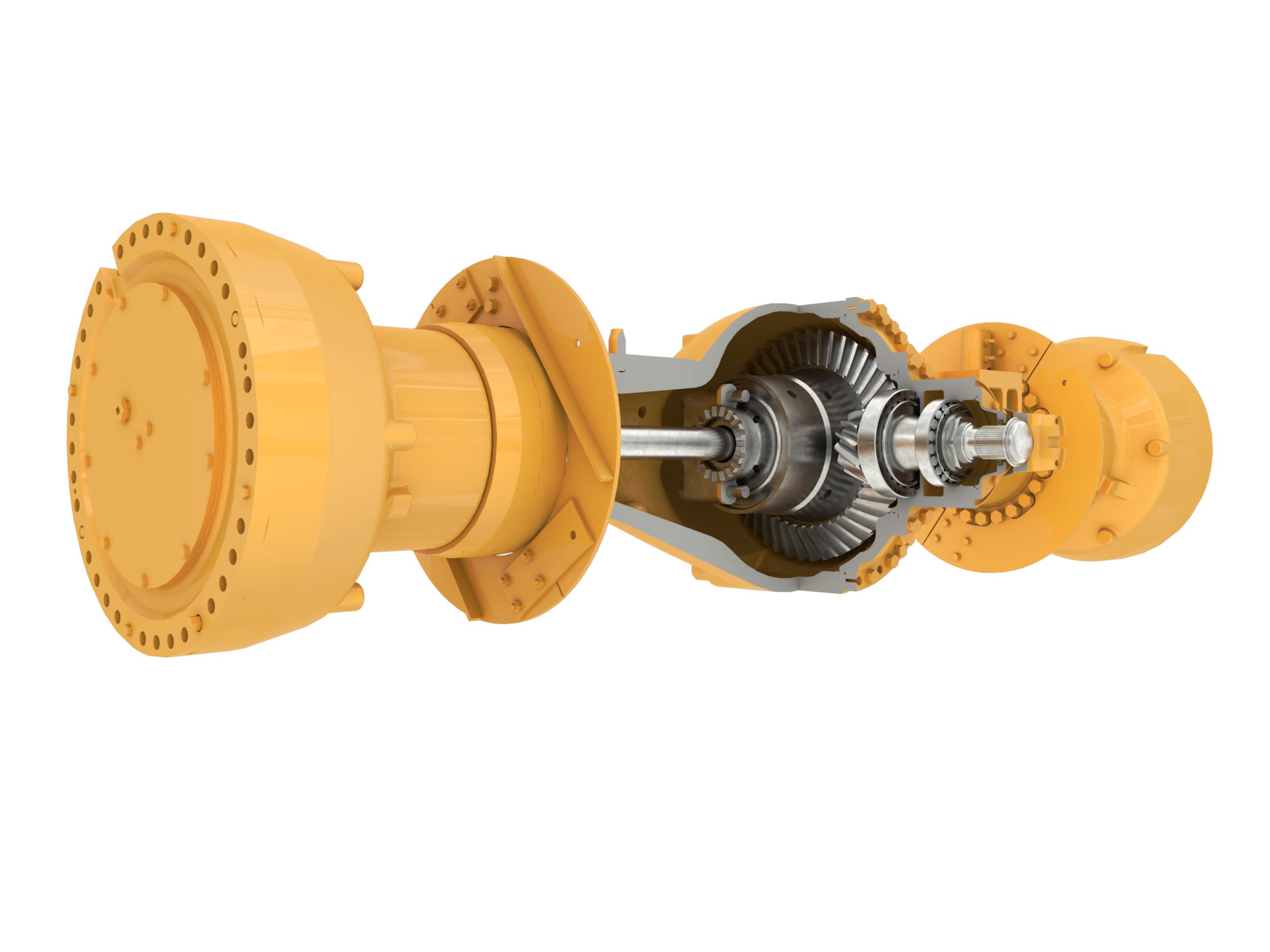
- Larger diameter axle shafts, the Cat locker differentials, improved duo cone labyrinth, thicker wheel at the spindle for increased strength.
- Improved final drive gear set to help reduce stress and enhance pitting life.
- Fan motor guard to help prevent bag wrapping.
- 5" higher efficiency fuel filter for cleaner fuel to the engine.
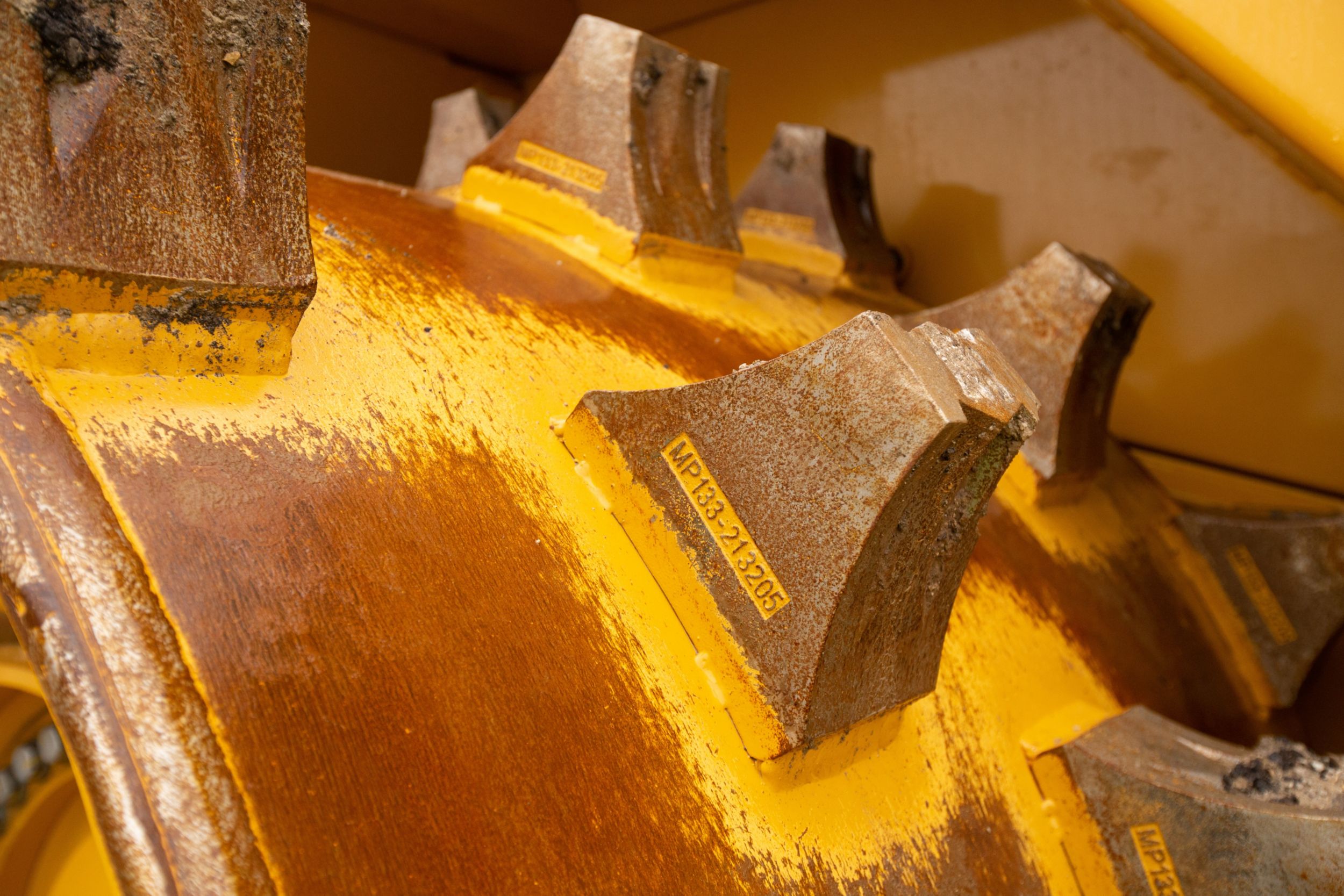
WHEEL TIPS BUILT TO PERFORM
- Designed specifically to complement Cat machines.
- Improves machine performance through longer wear life and maintaining traction.
- Five wheel and tip configurations are available to meet your particular application:
1) Paddle Tip – High performance and less fuel burn with more traction and less weight.
2) Plus Tip – Traditional design for increased side slope stability.
3) Combination Tip – Both paddle and plus tips help provide the best compromise of performance and fuel economy with side slope stability.
4) Diamond Tip – Longest life tip on the market with reputation of reliability that is world class in the waste tip industry.
5) Chopper Tip – These types of tips are recommended for wet/soft waste where chopping and/or traction is a large concern and abrasive wear life is not a major concern.
Data not available.
Standard Equipment
- NOTE
- Standard and optional equipment may vary. Consult your Cat dealer for details.
- POWER TRAIN
- Advanced Productivity Electronic Control Shifting (APECS)
- Air to air aftercooler
- Brakes, fully hydraulic, enclosed, wet multiple disc brakes
- Cat Clean Emission Module, insulated (Tier 4 Final/Stage V/Korea Stage V and Japan 2014)
- Electro hydraulic parking brake
- Engine, Cat C18: – Tier 4 Final/Stage V/Korea Stage V and Japan 2014 – Tier 3/Stage IIIA equivalent
- Fuel priming pump, electric
- Fuel to air cooler
- Ground level engine shutoff
- Guard (3 piece) transmission
- Heat shield, turbo and exhaust manifold
- Hydraulically driven demand fan
- Integrated braking
- Radiator, Aluminum Modular Radiator (AMR)
- Separated cooling system
- Starting aid (ether) automatic
- Throttle lock
- Torque converter with lockup clutch (LUC)
- Turbine precleaner, engine air intake
- Transmission, planetary, with 2F/2R speed range control
- Underhood ventilation system
- ELECTRICAL
- Alarm, back-up
- Alternator, 150 amp
- Batteries, maintenance-free (4-1,000 CCA)
- Converter, 10-15 amp, 24V to 12V
- Lighting system, halogen (front and rear)
- Lighting, access stairway
- Starter, electric (heavy duty)
- Starter lockout (ground level)
- Starting receptacle for emergency start
- Transmission lockout (ground level)
- OPERATOR ENVIRONMENT
- Air conditioner w/roof-mounted condenser
- Cab, sound-suppressed and pressurized
- Internal four-post rollover protective structure (ROPS/FOPS)
- Radio ready for (entertainment) includes antenna, speakers and converter (12V, 10-15 amp) 12V power port for mobile phone or laptop connection
- Camera, rear vision
- Coat and hard hat hooks
- Flip-up armrest
- Heater and defroster
- Horn, electric
- Hydraulic controls (floor mounted)
- Implement hydraulic lockout
- Laminated glass
- Light, (dome) cab
- Lunchbox and beverage holders
- Instrumentation, Gauges: – DEF fluid level (Tier 4 Final/Stage IV) – Hydraulic oil temperature – Speedometer/tachometer – Torque converter temperature
- Instrumentation, Warning Indicators: – Action alert system, three category – Axle/brake oil temp, front – Brake oil pressure – Electrical system, low voltage – Engine failure malfunction alert and action lamp
- Mirrors, rearview (externally mounted)
- Parking brake status
- Radio, CB (ready)
- Seat, Cat Comfort, (cloth) air suspension
- Seat belt, retractable, 76 mm (3") wide
- STIC Control System with steering lock
- Sun visor, front
- Glass (window) - rubber mounted glass
- Transmission gear (indicator)
- Vital Information Management System (VIMS) with graphical information display: external data port, customizable operator profiles
- Wet-arm wipers/washers (front and rear)
- Intermittent wipers (front and rear)
- WHEELS
- Wheels, paddle, plus, combination, and diamond wheel configurations
- GUARDS
- Guards, axle (front and rear)
- Guards, cab window
- Guards, crankcase and power train, hydraulically powered
- Guards, rear fan and grill
- BLADES
- Bulldozer arrangement is included in the standard equipment. Bulldozer blades are optional.
- FLUIDS
- Antifreeze, premixed 50% concentration of extended life coolant with freeze protection to –34° C (–29° F)
- OTHER STANDARD EQUIPMENT
- Auto Blade Positioner (ABP)
- Demand fan/swing out (hydraulic reversible)
- Doors, service access locking
- Ecology drains for engine, radiator, hydraulic tank
- Electronic clutch pressure control and remote mounted pressure taps
- Emergency platform egress
- Engine, crankcase, 500 hour interval with CJ-4 oil
- Fuel tank, 793 L (210 gal)
- Hitch, drawbar with pin
- Hoses, Cat XT™
- Hydraulic oil cooler
- Hydraulic, steering and brake filtration/screening system
- Oil sampling valves
- Product Link™ - Cellular
- Stairways, fixed-L/R (rear access)
- Steering, load sensing
- Vandalism protection caplocks
- Venturi stack
Optional Equipment
- NOTE
- Standard and optional equipment may vary. Consult your Cat dealer for details.
- Various blades:
- Straight blade
- U-blade
- Semi U-blade
- Various tip and wheel arrangements:
- Paddle
- Plus
- Diamond
