
Overview
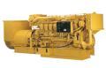
The 3516B Marine Generator Set incorporates a separate circuit aftercooling (SCAC) or sea water aftercooling (SWAC) system for all configurations. The primary advantage of the SCAC systsem is reduced aftercooler corrosion since no sea water circulates through the aftercooler. Many other improvements on these engines contribute to minimizing owning and operating costs. A strengthened fuel injection actuation system and rear gear train maintain reliability and durability while providing higher injection pressures. The 3516B also features thermo-laminated heat shields on all marine configurations to maintain surface temperatures below Marine Classification Society regulations.
Specifications
Units:
| Minimum Rating | 1180 eKW (1475 kVA) |
| Maximum Rating | 1825 eKW (2281 kVA) |
| Frequency | 50 Hz or 60 Hz |
Benefits & Features
Improved fuel economy
Reduced visible and gaseous emissions
Enhanced diagnostic and monitoring capabilities
June 16, 2025
Specifications
Units:
| Minimum Rating | 1180 eKW (1475 kVA) |
| Maximum Rating | 1825 eKW (2281 kVA) |
| Frequency | 50 Hz or 60 Hz |
| Speed | 1000 rpm, 1200 rpm, 1500 rpm, 1800 rpm |
| Emissions/Fuel Strategy | IMO I, IMO II (1600 eKW @ 50 hz only) |
| Configuration | Vee 16, 4-Stroke-Cycle Diesel |
| Bore | — |
| Stroke | — |
| Displacement | — |
| Weight | 11354 kg (25030 lb) to 13538 kg (29845 lb) |
| Length | 5076 mm (199.8 in) to 5611 mm (220.9 in) |
| Width | 1703 mm (67.1 in) to 2144 mm (84.4 in) |
| Height | 2053 mm (80.8 in) to 2100 mm (82.7 in) |
Benefits & Features
Improved fuel economy
Reduced visible and gaseous emissions
Enhanced diagnostic and monitoring capabilities
Increased rated output with no reduction in reliability
Data not available.
Standard Equipment
- AIR INLET SYSTEM
- Separate Circuit aftercooler core, corrosion resistant coated (air side) Air cleaner, regular duty Dual Turbochargers, 152 mm (6 in) OD straight connection
- CONTROL SYSTEM
- Caterpillar A-III Electronic Engine Control, with Electronic Unit Injector Fuel System Rigid Wiring Harness (10 amp DC power required to drive Electronic Engine Control Module)
- COOLING SYSTEM
- Oil cooler Thermostats and housing, full open temperature 92 C (198 F) Jacket water pump, gear driven, centrifugal Auxiliary fresh water pump Expansion tank Auxiliary sea water pump, centrifugal, non-self-priming
- EXHAUST SYSTEM
- Dry gas tight exhaust manifolds with heat shields Dual Turbochargers with watercooled bearings and heat shields Exhaust outlet, vertical, 305 mm (12 in) round flanged outlet on engines @ 1500 or 1800 rpm Exhaust outlet, vertical, 203 mm (8 in) round flanged outlet on engines @ 1200 or 1000 rpm
- FLYWHEELS & FLYWHEEL HOUSINGS
- Flywheel, SAE No. 00, 183 teeth Flywheel housing, SAE No. 00
- FUEL SYSTEM
- Fuel filter, RH, with service indicators
- Fuel transfer pump
- Electronically Controlled Unit Injectors
- INSTRUMENTATION
- Overspeed shutdown notification light
- Emergency stop notification light
- Prelube override
- Shutdown override
- Graphical Unit (Marine Power Display) for analog or digital display of:
- Engine oil pressure, Engine water temperature, Fuel pressure System, DC voltage, Air inlet restriction, RH & LH exhaust temperature, Fuel filter differential, Oil filter differential, Service meter, Engine speed, Instantaneous Fuel Consumption, Total Fuel Consumed, Engine Control Switch (4 position), Alarms are prioritized, Overspeed shutdown notification light, Emergency stop notification light, Prelube override, Shutdown override
- LUBE SYSTEM
- Crankcase breather, Top mounted Oil filter, RH Oil filler and dipstick, RH Deep sump oil pan Oil pump, gear type
- MOUNTING SYSTEM
- Rails, engine mounting, engine length, industrial type, 254 mm (10 in), C-channel
- POWER TAKE-OFFS
- Accessory drive Lower RH, Lower LH Front housing, Two-sided
- PROTECTION SYSTEM
- A-III Electronic Monitoring System provides customer programmable engine de-ration strategies to protect against adverse operating conditions
- Emergency stop push button (located in Electronic Instrument Panel) Safety shutoff protection:
- GENERAL
- Vibration damper and guard Paint, Caterpillar Yellow engine with black rails. Lifting eyes
- NOTE: 1. Engines for heat exchanger cooling do NOT include heat exchanger. 2. When used with competitive generator, a TVA is recommended. An alternative vibration damper may be required. 3. Engine is wired for auto start stop.
Optional Equipment
- AIR INLET SYSTEM
- Air Cleaner Removal
- Remote Air Inlet Adapters
- CHARGING SYSTEM
- Battery Chargers
- Charging Alternators
- CONTROL SYSTEM
- Load Sharing module
- Local speed throttle control
- COOLING SYSTEM
- Water level switch gauge
- Coolant level sensors
- Connections
- Keel Cooling Conversions
- Radiator cooling conversion
- Heat exchangers
- Auxiliary water pumps
- Sea water pump removal
- Air separator
- EXHAUST SYSTEM
- Exhaust outlet
- Flexible fittings
- Elbows
- Flanges
- Flange and exhaust expanders
- Mufflers
- FUEL SYSTEM
- Fuel Cooler
- Fuel priming pumps
- Flexible fuel lines
- Rigid Fuel Lines
- Primary fuel filter
- Fuel level switch
- GENERATORS AND GENERATOR ATTACHMENTS
- Low voltage connection
- Generator conversion
- RFI filter
- Bearing temperature detectors (RTD
- Manual voltage control
- Air filter
- INSTRUMENTATION
- PL1000T Communication Module
- PL1000E Communication Module
- Customer Interface Box
- Thermocouples
- Remote panel display
- Remote cylinder temperature display
- LUBE SYSTEM
- Oil Pan
- Oil pan accessories
- Sump pumps
- Prelubrication Options
- Lubricating oil
- Centrifugal Oil Filter
- MOUNTING SYSTEM
- Vibration isolators
- Rails
- POWER TAKE-OFFS
- Flywheel guard
- Flexible coupling
- Coupling hub
- Front housing accessories
- Upper left hand front location
- Upper left hand rear location
- Upper right hand front location:
- Upper right hand rear location
- Lower left hand front location
- Front housing accessory drives
- Front power take-offs
- Crankshaft pulleys
- Damper guard removals
- PROTECTION SYSTEM
- Air inlet shutoffs
- Switches and contactors
- Explosion relief valve
- Sensors
- SPARE PART KITS
- Engine Parts Kits
- STARTING SYSTEM
- Starting motors or barring divice
- Air starting motors options
- Starting aids
- Battery sets - 24 volt - Dry
- Battery rack
- GENERAL
- Tool set
- Caterpillar datalink wire